Debugging item: LED display
Countermeasure analysis and solution description
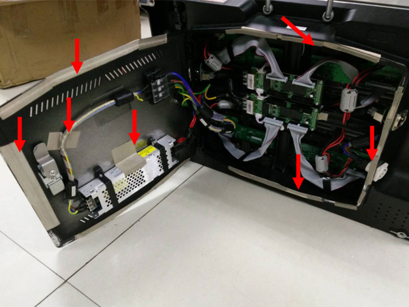
1. Scrape insulating varnish off the box body and the edge of back cover, stick the conductive foam to the back cover to contact the box body, shown as the picture below.
And then, stick conductive cloth between the shell of power and the iron shell of back cover so that they closely contact each other.
Don't fix the AC input wire on the metal shell of power, wire layout should be like what the picture shows. For mass production, other better methods can be chosen to fix the AC wire.
--------------------------------------------------------------------------------------------------------------------
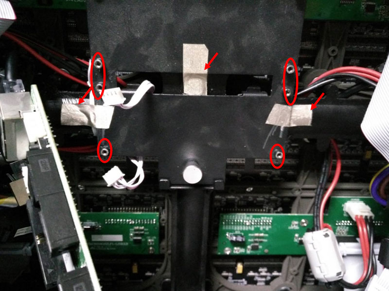
2. Scrape the insulating varnish off the picture-showing three locations of the iron board and stick conductive cloth there linked with the box body.
Besides, scrape the insulating varnish off the poles fixing the controlling board, shown as below.
Don't paint insulating varnish where the iron board and the box body contact, when run mass production.
---------------------------------------------------------------------------------------------------------------------
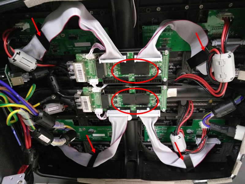
3. Remove the eight flat ferrite cores off the ribbon cables, replace the ferrite cores with four wideband wave-absorbing sheets installed at the middle area of cables.
Adhere wideband wave-absorbing sheets to chips on the control board.
Conduction testing data before debugging
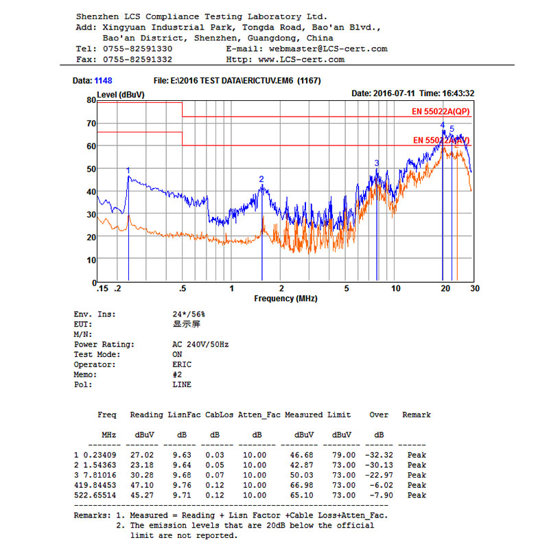
--------------------------------------------------------------------------------------------------------------------
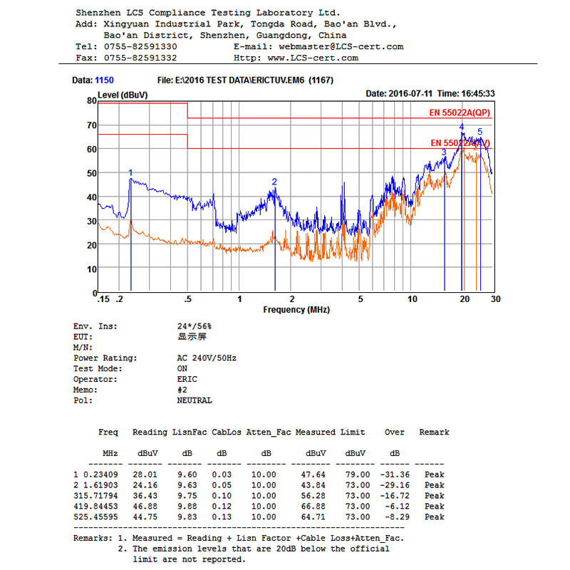
Conduction testing data after debugging
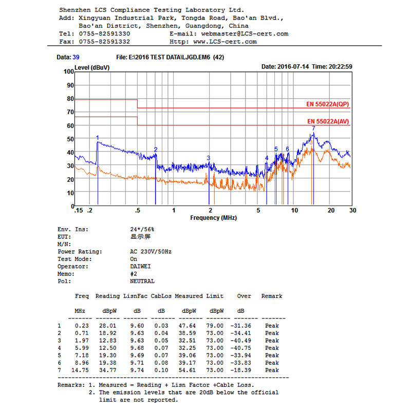
--------------------------------------------------------------------------------------------------------------------
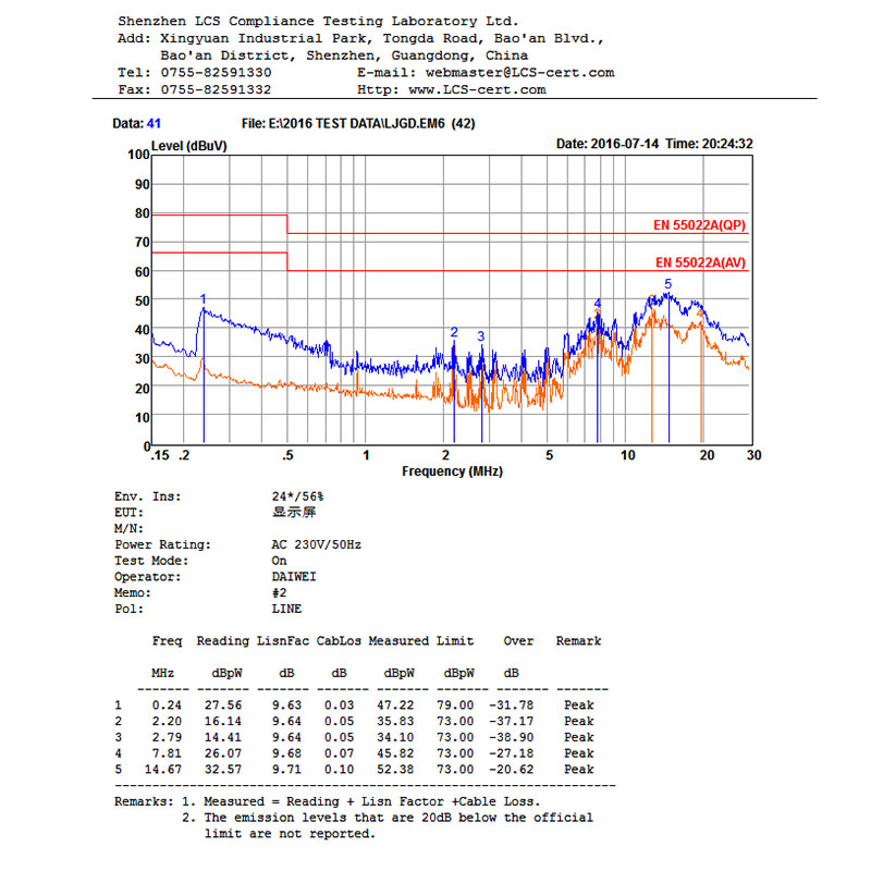
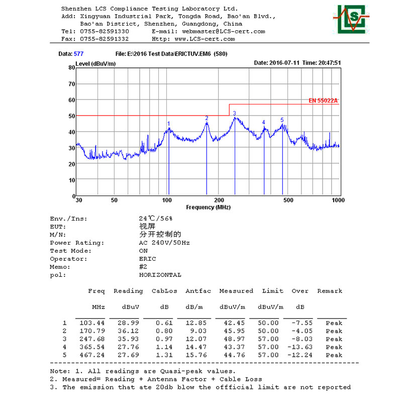
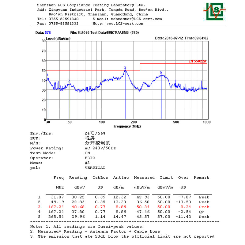
Radiation testing data before debugging
--------------------------------------------------------------------------------------------------------------------
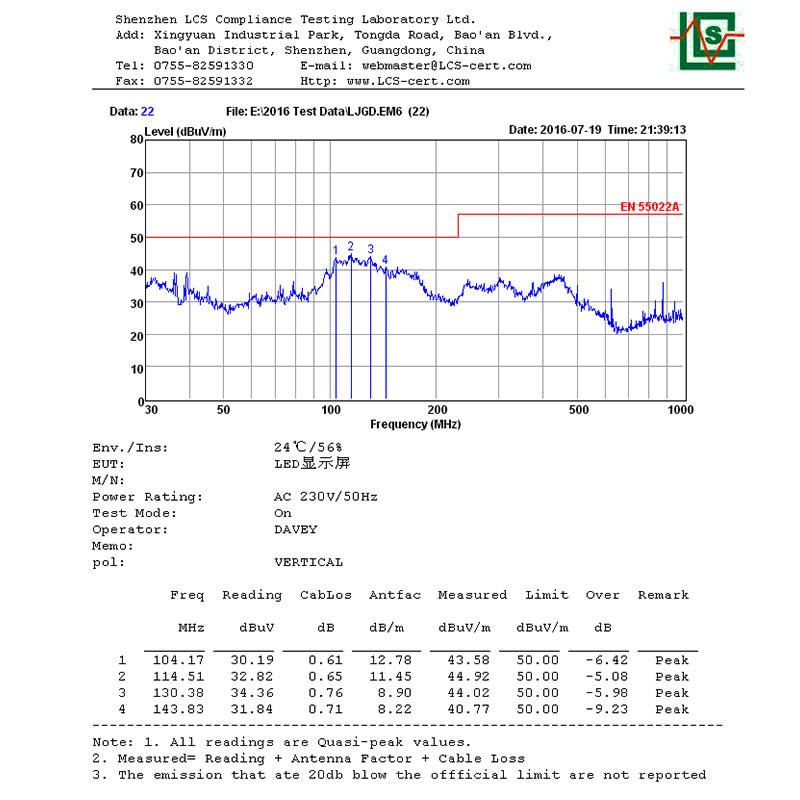
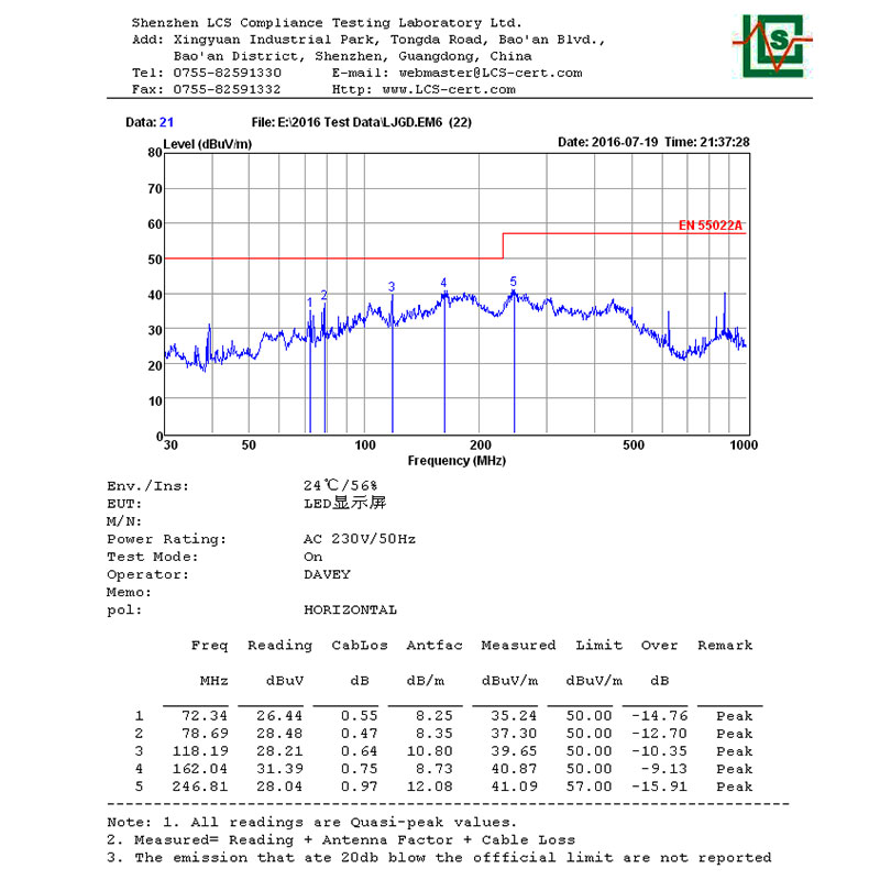
Radiation testing data after debugging
--------------------------------------------------------------------------------------------------------------------
