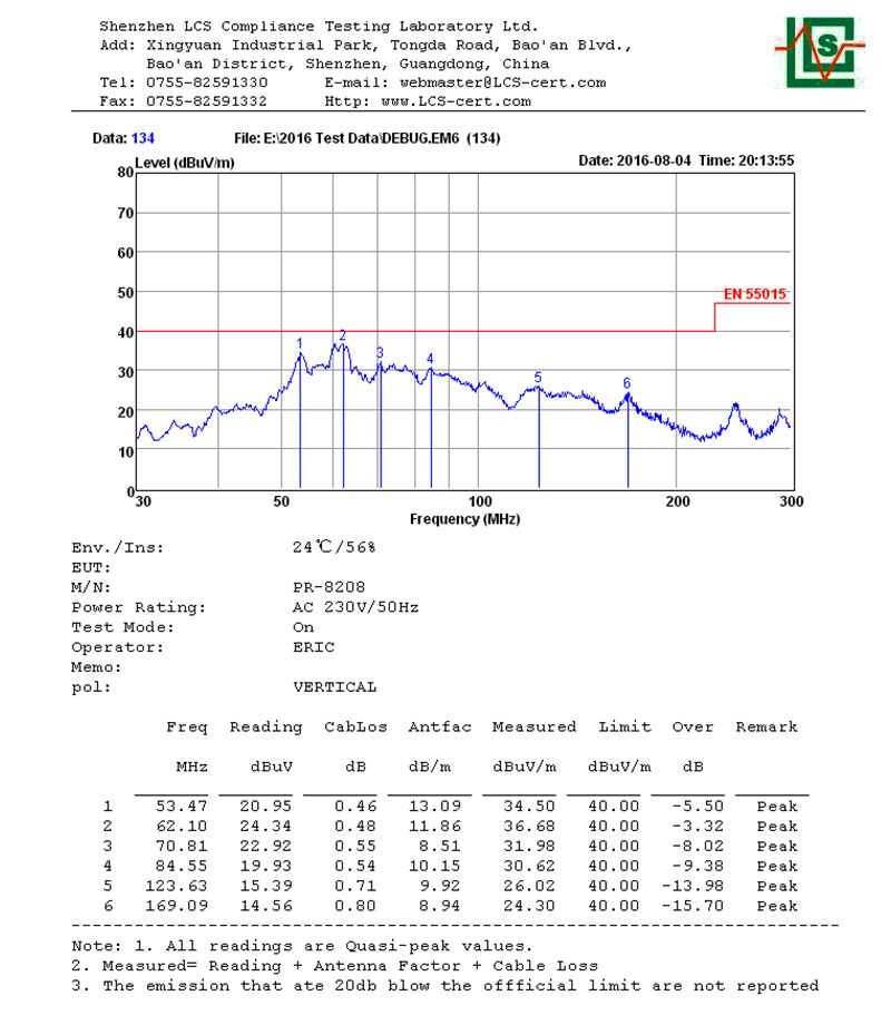
Debugging item: PR-8208
Countermeasure analysis and solution description
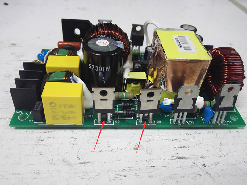
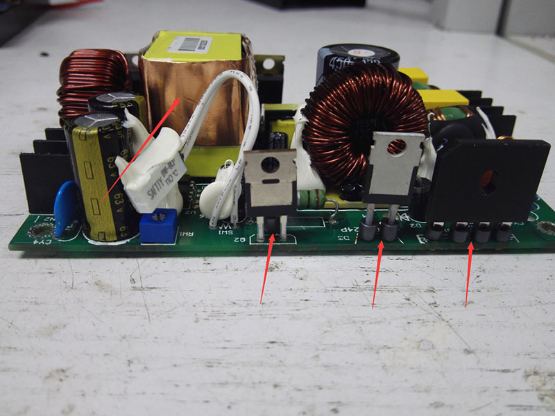
1. Shield the transformer with copper foil and link it with primary earth wire.
Add a small ferrite bead to every pin of the bridge rectification, the middle pin of Q2/Q3/Q6, as well as each of the two pins of D3.
--------------------------------------------------------------------------------------------------------------------
2. To AC input end, add a filtering circuit consisting of a 0.33uF X capacitor + two 200uH differential inductors.
--------------------------------------------------------------------------------------------------------------------
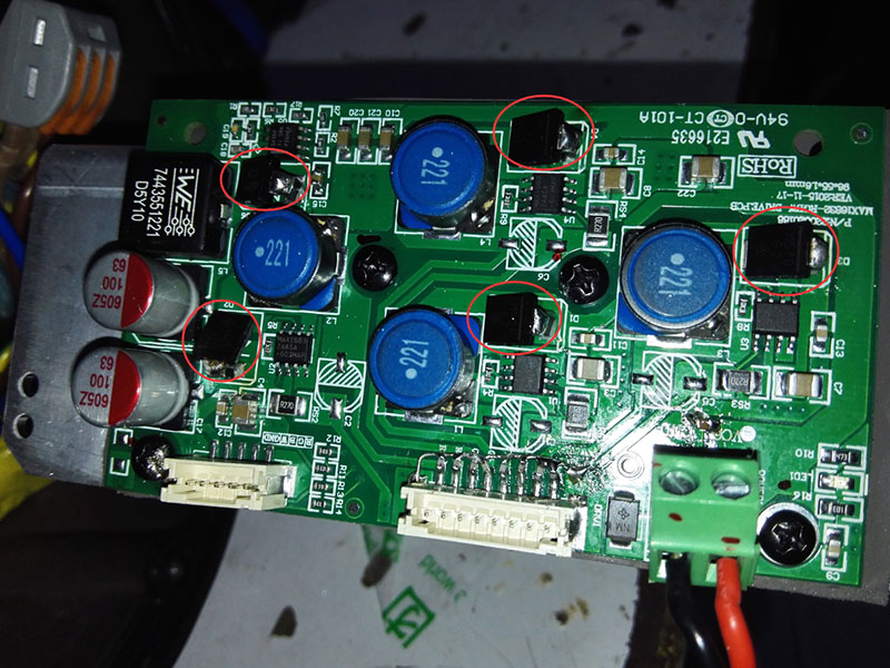
3. Contact a 151T ferrite bead in series to each of the five diodes shown in the picture,
and add a 100pF capacitor between earth and each signal wire of the output terminal.
--------------------------------------------------------------------------------------------------------------------
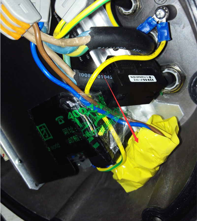
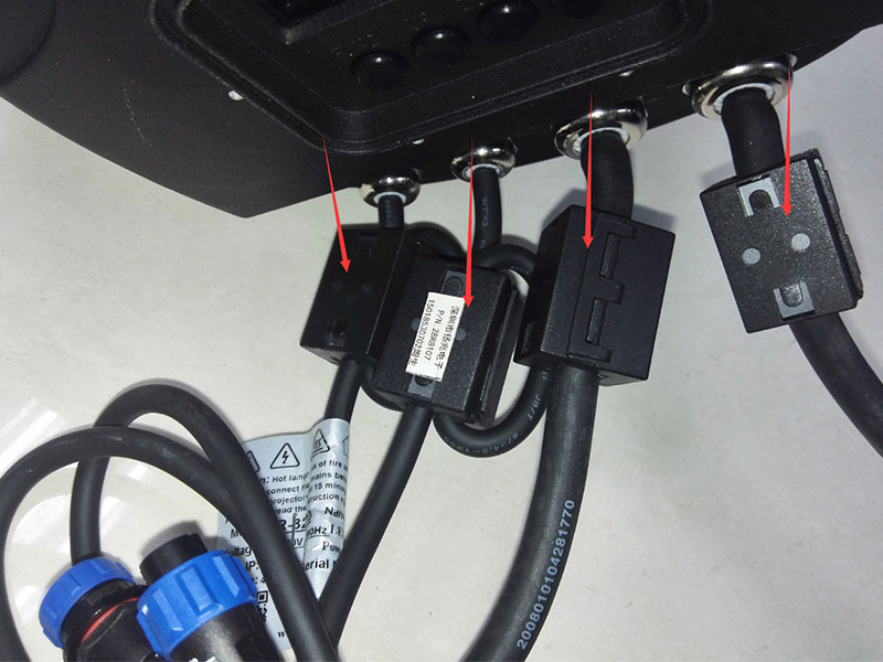
4. Add a ferrite core to each of the two AC lines, threading directly.
Add a ferrite core to each of the two signal lines, winding one turn.
--------------------------------------------------------------------------------------------------------------------
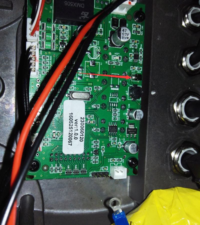
5. Contact a 221T ferrite bead in series with negative pole of the diode shown on the display board.
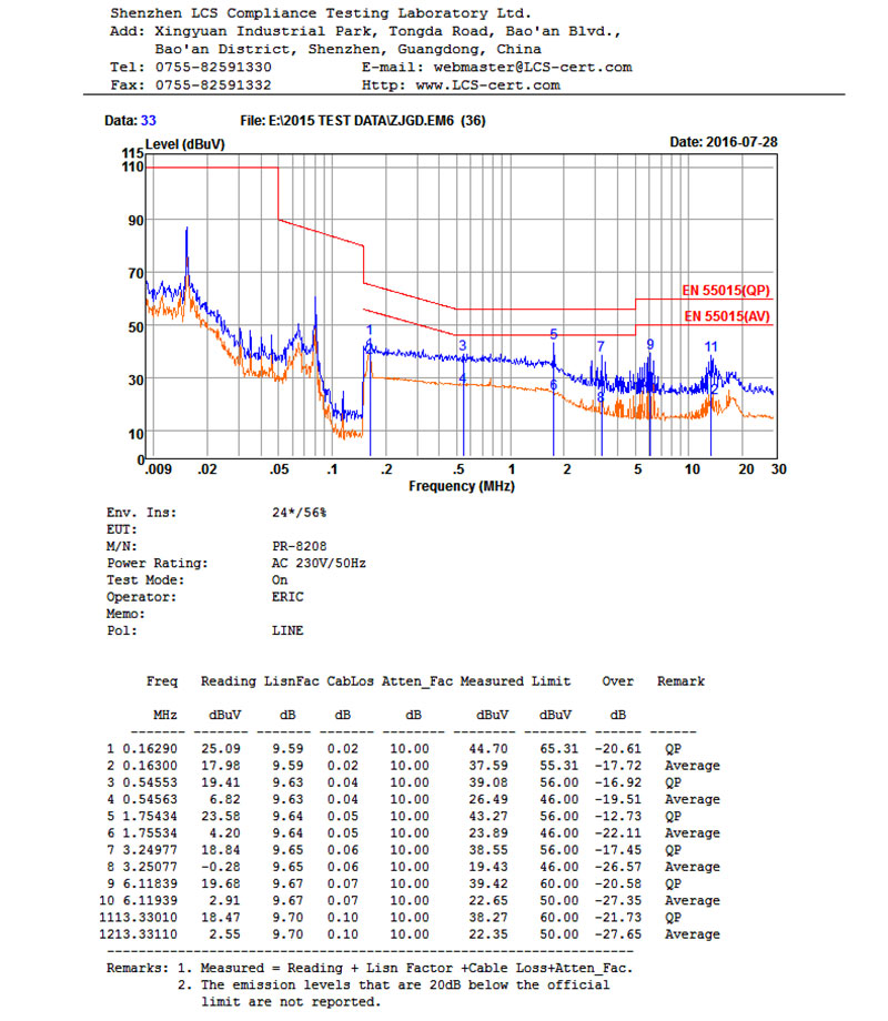
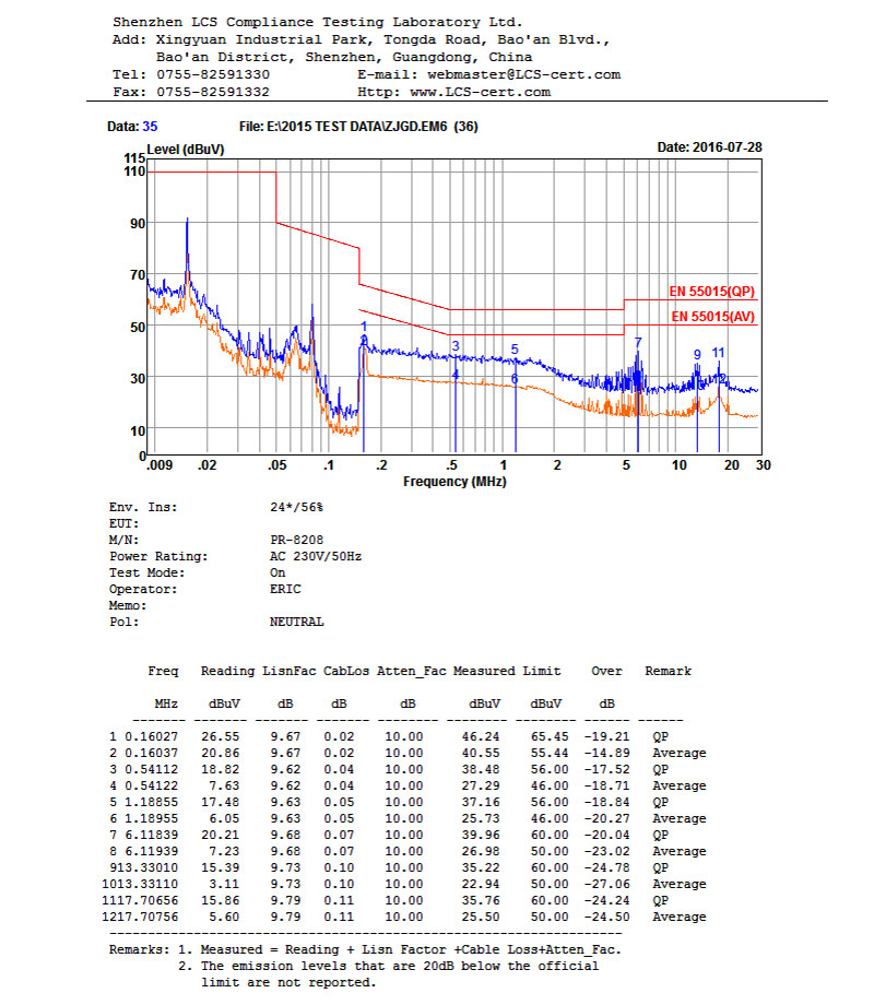
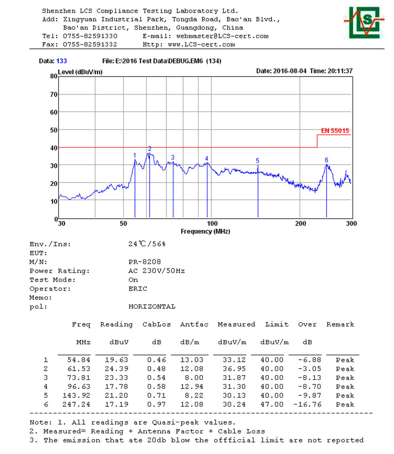
Testing data after debugging
-------------------------------------------------------------------------------------------------------------------
--------------------------------------------------------------------------------------------------------------------
--------------------------------------------------------------------------------------------------------------------
