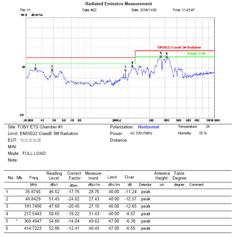
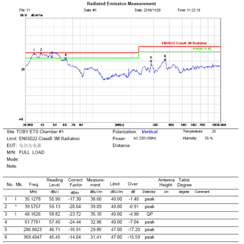
Debugging item: space radiation
Countermeasure analysis and solution description
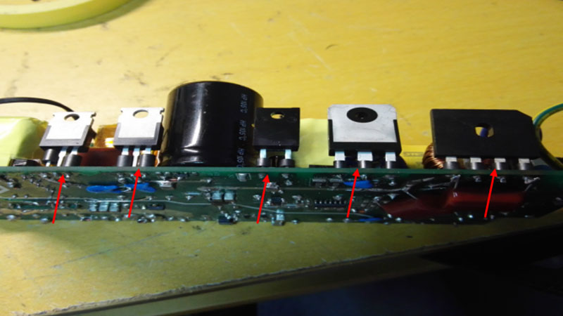
1. Contact a small ferrite bead in series at each pin of MOS tube, bridge rectifier and diode.
--------------------------------------------------------------------------------------------------------------------
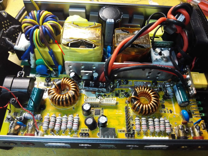
2. Change the filtering circuit of input end to the combinating filtering consisting of 1uF X capacitor + 35mH common mode inductor + 1uF X capacitor + 35mH common mode inductor. And add a ferrite core to AC wire, winding 8 turns(L/N/G be wound parallel.)
--------------------------------------------------------------------------------------------------------------------
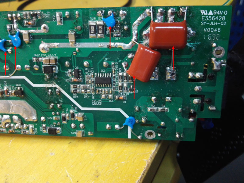
3. Parallel a 102 ceramic flat capacitor to S/D pin of both Q18 and Q19.
Parellel a 101 ceramic flat capacitor to S/D pin of switch MOS and adjust its drive resistor as 68ohm.
After rectification, add a π type filtering circuit, consisting of CBB224 capacitor + 200uH differential inductor + CBB224 capacitor
--------------------------------------------------------------------------------------------------------------------
4. Shield L2 with copper foil in both tansversal and longitudinal directions, and link it to earth.
Add a 102 capacitor between output positive end and earth, and a 104 capacitor between negative end and earth.
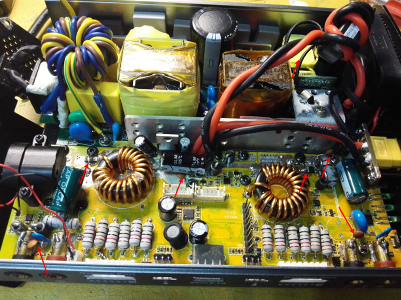
Contact a BEAD1812S90T ferrite bead in series to every positive pole shown below of the power.
--------------------------------------------------------------------------------------------------------------------
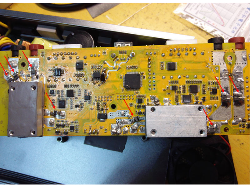
5. Contact a BEAD1812S121A90T ferrite bead in series to both two poles of output.
Contact a BEAD1812S121A90T ferrite bead in series to both input and output pins of IC shown in the picture.
Contact a BEAD1812S121A90T ferrite bead in series to output pins of the two inductors.
--------------------------------------------------------------------------------------------------------------------
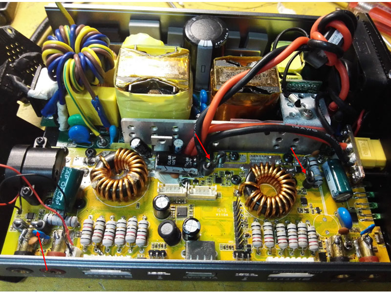
6. Add a small ferrite core to both ends of the three jumper wires of output.
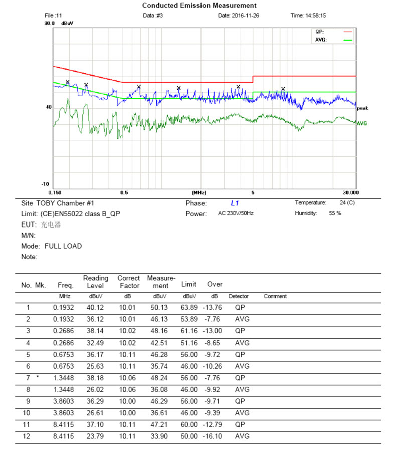
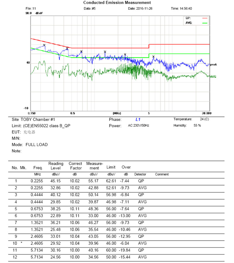
Testing data of conduction
--------------------------------------------------------------------------------------------------------------------
--------------------------------------------------------------------------------------------------------------------
--------------------------------------------------------------------------------------------------------------------
